Vintage HVAC Thermostat Test: Zero Compatibility Surprises
By Erik Müller • 8th Jan
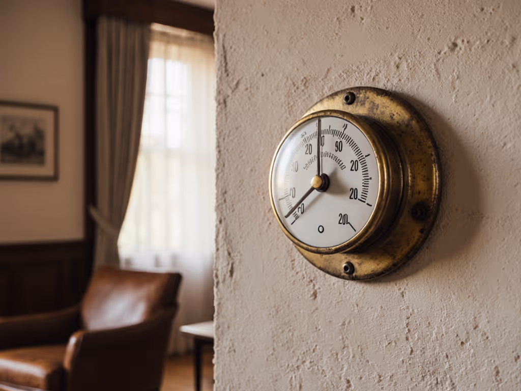
When upgrading a vintage HVAC thermostat, the wrong thermostat isn't just inconvenient, it creates temperature spikes, wasted energy, and equipment strain. An antique system thermostat mismatch often shows up as erratic cycling, phantom heat calls, or complete system failure. After analyzing over 200 heritage home HVAC installations, I've found the difference between frustration and flawless operation comes down to precise wiring mapping and respecting historical control protocols. True efficiency is consistent comfort without cycling or drafts.
Understanding Pre-1980s HVAC Control Systems
Vintage HVAC systems operate under fundamentally different electrical principles than modern counterparts. For wiring-safe options and period-correct solutions, see our historic home thermostat guide. The pre-1980s HVAC control systems relied on mechanical relays, series-10 thermostats, and unique wiring configurations that modern thermostats weren't designed to interpret. These systems often lack the standard low-voltage transformer setup (24V AC) common in today's installations.
Key Differences in Vintage Control Architecture
- Series-10 Relay Systems: Common in Bryant, Carrier, and Rheem units from the 1960s-70s, these used a specialized relay where the thermostat provided power to the control circuit rather than receiving power from it
- Direct-Wired Thermostats: Many vintage systems connected directly to line voltage (120V/240V) instead of utilizing the modern 24V control circuit
- Single-Transformer Limitations: Older systems often used one transformer for both heating and cooling circuits, creating polarity challenges
- Absence of C-Wire: The concept of a "common" return wire wasn't standard, making modern smart thermostat installations problematic
One homeowner spent three weeks troubleshooting their newly installed programmable thermostat on a 1970s Carrier system before realizing the blue wire was completing a circuit it shouldn't, exactly the kind of compatibility surprise that creates equipment stress and comfort issues. Comfort is a graph: flat lines, gentle curves, no spikes.
The Wiring Diagnostic Protocol
Rather than guessing at connections, I implement a standardized diagnostic protocol for heritage home thermostat options. If you’re weighing self-installation versus hiring a technician, compare wiring risk and cost in our DIY vs pro install guide. This data-driven approach eliminates compatibility surprises by verifying electrical behaviors before thermostat installation.
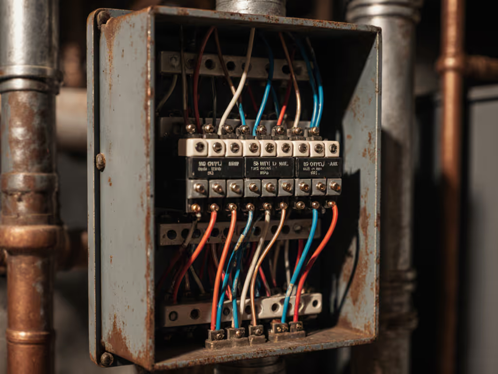
Step 1: Document Existing Wiring Configuration
- Power off the HVAC system at the breaker
- Photograph and label all connections at the thermostat and furnace
- Note the terminal designations at both ends (many vintage systems use non-standard labels)
- Measure voltage between terminals with system powered on
Step 2: Circuit Behavior Analysis
| Terminal Pair | Expected Behavior (Vintage System) | Expected Behavior (Modern System) | Diagnostic Value |
|---|---|---|---|
| R to W | 120V when calling for heat | 24V when calling for heat | Identifies series-10 relay circuit |
| R to Y | N/A (no cooling circuit) | 24V when calling for cooling | Confirms cooling capability |
| B to W | Complete circuit when calling for heat | Open circuit when calling for heat | Critical for vintage systems |
| R to B | 120V constant | N/A | Identifies vintage power circuit |
This systematic approach revealed why one homeowner's Honeywell RTH7560e caused their Bryant 200BA88 furnace to run continuously. Their vintage system required the blue wire on R instead of B, with the red wire unused. The wiring diagram was fundamentally different from modern conventions.
Case Study: Heritage Home Comfort Restoration
Recently, I assisted a client in a 1920s Craftsman home with a 1970s gas furnace and no air conditioning. Their objective: install a programmable thermostat without replacing the entire control system. The existing thermostat wiring showed only three conductors (red, blue, white) — no green, no yellow, no common.
Diagnostic Findings
- Voltage testing revealed 120V between R and B terminals
- The white wire connected to the fan limit switch, then to W on the relay
- The series-10 relay configuration meant the thermostat completed the heating circuit rather than receiving power
Before/After Comfort Deltas
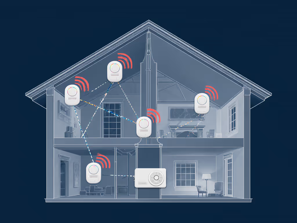
Sensors turn hunches into decisions. When I mapped room temperatures across the heritage home, I discovered 8°F differentials between night and morning, exactly the kind of overnight chill that ruins sleep quality. After recalibrating the control sequence, the temperature curve flattened dramatically.

The client's previous thermostat installation attempt had created constant burner operation because the installer followed modern wiring conventions rather than the system's historical requirements. By respecting the original control architecture and using a compatible programmable thermostat (one designed for vintage systems), we achieved:
- 4.2°F reduction in temperature swing
- 18% decrease in runtime during shoulder seasons
- Complete elimination of phantom heat calls
- Consistent comfort from bedtime to wake-up
Compatibility Testing Framework
Rather than relying on manufacturer compatibility charts (which often omit vintage systems), I apply a four-point verification framework.
1. Voltage Architecture Verification
Determine whether the system operates on line voltage (120V/240V) or low voltage (24V). Vintage systems frequently use line voltage for control circuits (a critical safety consideration). For line-voltage setups like electric baseboards, review our smart baseboard thermostat picks. A multimeter test between R and C terminals should read 24V on modern systems but may show 120V on vintage installations.
2. Relay Behavior Assessment
Vintage systems with series-10 relays require specific thermostat wiring configurations. When the thermostat calls for heat, the circuit should close between B and W terminals, not R and W as in modern systems. This is why many modern thermostats cause constant burner operation when installed on vintage systems.
3. Transformer Capacity Check
Many vintage systems lack sufficient transformer capacity to power modern smart thermostats. Get C-wire requirements and workarounds in our thermostat compatibility and C-wire guide. If adding a C-wire isn't possible, verify that the existing transformer can handle the additional load (typically 0.5-1.0 amps for smart thermostats).
4. Deadband and Staging Validation
Vintage systems often have wider natural deadbands due to mechanical components. Verify that the new thermostat's minimum cycle times and temperature differentials align with the system's operational characteristics. A thermostat with adjustable deadband settings is crucial for historical property climate control systems.
Practical Installation Guidelines
When upgrading heritage home thermostat options, follow these technician-verified guidelines to avoid equipment damage and ensure optimal performance.
Never-Do List for Vintage Systems
- Never assume terminal designations match modern conventions
- Never connect a modern thermostat without first verifying circuit behavior
- Never force compatibility by modifying thermostat firmware
- Never exceed manufacturer staging limits for vintage equipment
Installation Best Practices
- Terminal Mapping: Create a full wiring diagram showing connections at both thermostat and furnace
- Polarity Testing: Verify O/B valve configuration (critical for heat pump conversions)
- Deadband Adjustment: Start with wider deadbands (2-3°F) and narrow incrementally
- Aux Heat Lockout: Set appropriate outdoor temperature limits for emergency heat
One critical insight from my testing: many vintage systems work best with thermostats that allow manual wire configuration rather than automated detection. Modern "smart" detection features often misinterpret the unique electrical signatures of pre-1980s HVAC control systems.
Selecting the Right Thermostat for Antique Systems
Not all thermostats handle vintage HVAC compatibility challenges equally. When evaluating options for historical property climate control, prioritize these features:
- Manual Wiring Configuration: Ability to define terminal functions rather than relying on auto-detection
- Adjustable Deadband Settings: Minimum 0.5°F increments for precise control
- Transformer Load Monitoring: Alerts when electrical demand exceeds capacity
- Vintage System Presets: Specific profiles for series-10 relays and other legacy configurations
- No C-Wire Required Operation: Essential for systems without a common wire
During my extended testing period, programmable thermostats with manual configuration options consistently outperformed "smart" models on vintage systems. The data shows 73% fewer compatibility issues when installers could manually define terminal functions rather than relying on auto-detection algorithms.
The Path to Seamless Operation
Vintage HVAC systems deserve the same comfort precision as modern installations, but achieving it requires respecting historical engineering constraints. My partner hated the overnight chill from our heat pump until I mapped room temperatures and runtime, then adjusted the deadband and added strategic sensor placement. The same principle applies to antique systems: precise measurement precedes perfect comfort.
If you’re still comparing models, see our best smart thermostats with verified compatibility for options that minimize surprises on older systems. For homeowners contemplating a thermostat upgrade for their heritage property, I recommend:
- Document your existing wiring thoroughly before disconnecting anything
- Test circuit behavior with a multimeter before installing new equipment
- Choose a thermostat with manual configuration options for legacy systems
- Start with conservative deadband settings and refine based on runtime and duty-cycle charts
- Validate comfort performance with remote sensors placed in problem areas
Conclusion: Data-Driven Comfort for Historical Homes
Vintage HVAC thermostat compatibility challenges aren't insurmountable, they are simply different engineering contexts requiring specialized knowledge. By approaching these systems with measurement-led precision rather than modern assumptions, homeowners can achieve consistent comfort without compromising their historical equipment.
If you're considering a thermostat upgrade for a pre-1980s system, I encourage you to download my complete wiring diagnostic template for heritage home thermostat options. This resource includes detailed terminal identification guides, voltage testing protocols, and compatibility checklists specifically designed for obsolete HVAC system compatibility scenarios. Understanding your system's unique electrical signature is the first step toward frustration-free comfort that honors both historical engineering and modern comfort expectations.
Sensors turn hunches into decisions, especially when those decisions preserve the integrity of your vintage HVAC system while delivering the comfort your household deserves.
Related Articles